The top problems small engine technicians deal with daily are fuel system and electrical issues. Electrical issues pose the largest threat because technicians generally can’t see tangible evidence of what in the system is not working.
With electrical system complexity ever-growing in this industry, it’s important to grasp the fundamentals of voltage drop testing. Voltage drop testing makes electrical testing less stressful with a few simple tests that help you arrive at an accurate starting point, with the malfunctioning circuit (positive or negative) identified.
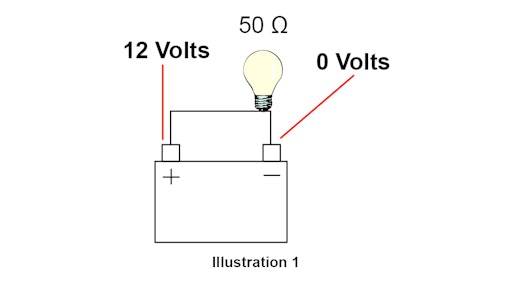
Wasted voltage. Whenever current (volume of electrons) passes through resistance, the voltage (electrical pressure) will drop based on how much resistance is present within that circuit. In a perfect world, the device we are trying to operate will receive all of the supplied voltage and convert it into useful work with nothing wasted. It would read 0 volts coming out the other side of the circuit (see Illustration 1).
However, circuits can develop additional resistance points that are going to short change the component when we want to have all the voltage in a circuit. It doesn’t matter if this extra resistance occurs on the positive or negative circuit, the end result will be the same (see Illustration 2).
Testing points. Electricity is lazy. We leverage the “path of least resistance” concept when performing voltage drop testing. Based on those facts, if we place our meter leads at the specific test points below while that circuit is in use, we can see how much electricity would rather bypass the system and go through the meter than be forced to travel through the circuit.
Positive circuit testing. With your meter set on Volts DC, place the red meter lead on the battery positive (+) post. With the black meter lead on the end point of the circuit you are testing (example: starter wire post), activate the circuit and watch the meter screen. A perfect reading is 0 to 0.5 Volts DC. Anything more than that indicates a restriction somewhere between the battery positive post and the contact point where the black meter lead was placed.
Negative circuit testing. With your meter set on Volts DC, place the red meter lead on battery negative (-) post. With the black meter lead on the end point of the circuit you are testing (example: starter-to-engine mounting bracket), activate the circuit and watch the meter screen. A perfect reading is 0 to 0.5 Volts DC. Anything more than that indicates a restriction somewhere between the battery negative post and the contact point where the black meter lead was placed.
With either of these tests, you should be able to conclude which circuit (positive or negative) is experiencing extra resistance and have a proper starting point for further investigation. From here you can perform the same test between every connection, wire and switch in that circuit until you ultimately find the root cause.
Tom Billigen is the customer education training manager at Briggs & Stratton Corporation.